Erosive Burning Design Criteria for High Power and
Experimental/Amateur Solid Rocket Motors
High Power Rocketry Magazine; January 2005
Author: Charles E. Rogers (CRogers168@aol.com)
This article covers erosive burning design criteria for high power and experimental/amateur solid rocket motors. Easy to implement design criteria are presented that allow high power and experimental/amateur rocketeers to determine the maximum length-to-diameter (L/D) ratio for a motor design, or the minimum diameter for the motor core to maximize propellant loading, for either non-erosive burning or max recommended erosive burning. The author proposes a unique approach of using combined core Mach number/core mass flux erosive burning design criteria, design criteria which are applicable whether the motor propellant is sensitive to velocity-based or mass flux-based erosive burning.
An innovative constant core mass flux core design is proposed by the author that maximizes the L/D of a motor design, or minimizes the motor port area (core cross-sectional area) for maximum propellant loading. Design criteria for the constant core mass flux core design are presented for both non-erosive and max recommended erosive burning.
Summary and Key Technical Results and Conclusions from the Article:
1) When high velocity or high mass flow hot gas from upstream combustion passes over a downstream burning surface in a solid rocket motor a local increase in propellant burning rate results. This local increase in propellant burning rate is called erosive burning.
2) There are two basic types of erosive burning; velocity-based erosive burning and mass flux-based erosive burning. Some propellants are more sensitive to the effect of the velocity of the hot gas flowing over the burning surface of the propellant (velocity-based erosive burning), some propellants are more sensitive to the effect of the mass flux of the hot gas over the burning surface (mass flux-based erosive burning). Mass flux is the mass flow rate per square inch of port area (core cross-sectional area) flowing over the propellant burning surface. Mass flux is calculated for a given location by taking the propellant mass flow rate from the upstream burning surfaces, divided by the port area.
3) The threshold values for core combustion gas velocity and core mass flux for the onset of velocity-based erosive burning and mass flux-based erosive burning are explained, and representative values are presented, including their variation with chamber pressure.
4) The threshold velocity for velocity-based erosive burning and the combustion gas velocity for max recommended erosivity can occur anywhere in the motor core, but they will be reached first in the highest velocity location in the core which is at the aft (nozzle) end of the core. The author recommends that the Mach number at the aft end of the core be used in place of core combustion gas velocity, as the core Mach number is a direct function of the ratio of the port area (core cross-sectional area) to the throat area. Representative core Mach number values for non-erosive and max recommended velocity-based erosive burning based on speed of sound values for the gas flow in the core for representative propellants are presented. The equation for core Mach number as a function of the port-to-throat area ratio is presented, including a summary core Mach number plot for quick hand calculations.
5) Based on the data and analysis presented in the article, the author recommends the following core Mach number and port-to-throat area ratio design criteria for velocity-based erosive burning for high power and experimental/amateur solid rocket motors:
Non-Erosive:
Core Mach Number £ 0.50
For g = 1.2; Ap/Ath ³ 1.36
Max Recommended Erosivity:
Core Mach Number = 0.70
For g = 1.2; Ap/Ath = 1.10
6) Note that for the max recommended erosivity core Mach number of 0.70 for velocity-based erosive burning that the port area is only 10% larger than the throat area. If the port area is reduced to the throat area, the motor will fire nozzleless; i.e. at ignition Mach 1 will be reached at the end of the core rather than at the throat. If the port-to-throat area ratio is reduced from 1.10 to 1.0, the velocity-based erosive burning will become very severe, not making it worth taking advantage of a further possible 10% reduction in port area.
7) Based on the data presented in the article, the author recommends the following core mass flux design criteria for mass flux-based erosive burning for high power and experimental/amateur solid rocket motors:
Non-Erosive:
pc = 400-600 psia; Core Mass Flux £ 1.0 lb/sec-in2
pc = 800 psia; Core Mass Flux £ 1.75 lb/sec-in2
pc = 1400 psia; Core Mass Flux £ 2.0 lb/sec-in2
Max Recommended Erosivity:
pc = 400 psia; Core Mass Flux = 2.0 lb/sec-in2
pc = 600 psia; Core Mass Flux = 2.5 lb/sec-in2
pc ³ 800 psia; Core Mass Flux = 3.0 lb/sec-in2
Core Mass Flux limits for Max Recommended Erosivity should not be exceeded unless Erosive Burning Characterization Tests are performed for propellant.
Based on the data presented in the article, it appears that a core mass flux £ 1.0 lb/sec-in2 will likely be non-erosive for all solid propellants at all chamber pressures. As noted above the max recommended erosivity core mass flux limits should not be exceeded unless erosive burning characterization tests are performed to determine the actual mass flux threshold value for the onset of mass flux-based erosive burning, and to determine a reasonable maximum mass flux limit for mass flux-based erosive burning.
8) Burn rate data from erosive burning characterization tests performed as part of the CSXT motor development program are presented, which confirm with limited data the non-erosive threshold core mass flux limits presented above. A summary plot is included where the increase in burn rate with core mass flux (once the threshold core mass flux for erosive burning is exceeded) can clearly be seen.
9) The author proposes a design methodology where non-erosive internal ballistics solid rocket motor simulation programs are combined with the erosive burning design criteria presented in the article. This method takes advantage of the large body of non-erosive internal ballistics solid rocket motor simulation programs available to high power and experimental/amateur rocketeers, by taking the application of these programs to a new level through the application of erosive burning design criteria to the design of the motors run on the simulation programs. Using the combined core Mach number/core mass flux erosive burning design criteria presented in the article, the experimental/amateur rocketeer can design solid rocket motors which will have little or no erosive burning. These solid rocket motor designs can then be run on existing non-erosive internal ballistics simulations for accurate predictions of the motor thrust-time curve.
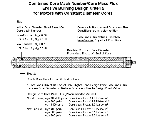
10) In the article the author proposes using a unique approach of combined core Mach number/core mass flux erosive burning design criteria for high power and experimental/amateur solid rocket motors. The combined core Mach number/core mass flux design criteria, and the two-step process in applying the design criteria are presented in the figure below.

All rights reserved. Used with permission.
A major advantage of using combined core Mach number/core mass flux erosive burning design criteria for either non-erosive or max recommended erosivity motor designs is that irregardless of whether the motor propellant is sensitive to velocity-based or mass flux-based erosive burning, provisions for both have been included as both core Mach number limits and core mass flux limits have been considered.
Note that an important analysis technique presented by the author and included in the figure above is to simplify the calculations for the core mass flux at the aft end of the core (the “core mass flux” for the motor), by calculating the core mass flux for ignition only, and basing the calculated core mass flux on the propellant non-erosive burn rate. The highest core mass flux, and thus the highest mass flux-based erosive burning will be at ignition. If the core mass flux limit for non-erosive burning is not exceeded, then the fact that the core mass flux calculations were done assuming a non-erosive propellant burn rate will have no effect since erosive burning will not be present. Basing the core mass flux calculations on the propellant non-erosive burn rate provides easy to use erosive burning design criteria, which through experience experimental/amateur rocketeers can use to calibrate what level of core mass flux based on the non-erosive propellant burn rate produces an acceptable level of erosive burning for their propellants.
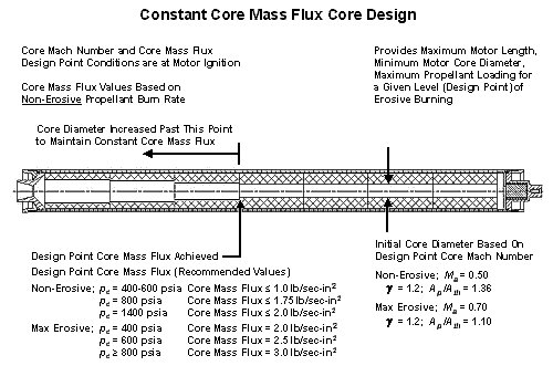
11) In the article an improved solid rocket motor core design proposed by the author is presented, that for a given level of erosivity maximizes the L/D of a motor, or maximizes the amount of propellant installed in a motor for a given length. This constant core mass flux core design is presented in the figure below. Once a level of erosivity is established for the overall motor design, the constant core mass flux core design maximizes the amount of installed propellant to maximize the total impulse of the motor.

All rights reserved., Used with permission.
As shown in the figure above, when using the constant core mass flux core design, once a design point core mass flux is achieved, the core is then opened up (the core diameter is increased) to maintain the same core mass flux down the rest of the core. As more propellant burning surface area is added down the core, the core has to be proportionately opened up to hold the core mass flux constant.
For the BATES grain generic motor design presented in the figure above, the core mass flux versus motor length will “stair-step” in discrete steps as each subsequent grain core diameter increases based on the core mass flux halfway down the length of each grain. Note that the constant core mass flux core design can also be used for monolithic grains, where the port area can be gradually increased once the design point core mass flux is achieved, versus the step-wise increase in core diameter for a motor with BATES grains.
This article was Part 6 of The Solid Rocket Motor series of articles.
Other articles in The Solid Rocket Motor series:
Performance Analysis of the Ideal Rocket Motor, January 1997
Parts 1 and 2
Solid Propellant Selection and
Characterization, February (A) 2001 and February (B) 2001
Part 3
Solid Propellant Grain Design and Internal
Ballistics, October/November 2002
Parts 4 and 5
Departures from Ideal Performance for Conical
Nozzles and Bell Nozzles, Straight-Cut Throats and Rounded Throats,
October 2004 and November 2004
Part 6
Erosive Burning Design Criteria For High Power and
Experimental/Amateur Solid Rocket Motors, January 2005